
Pattern 1 (Layout Guidance)
FLASH animation of Layout Guidance pattern
Description
This pattern refers to the availability of layout conventions or advice to organize the various model elements on a canvas. These include indications on the orientation, alignment and spacing of model elements in the space.
Purpose
To reduce clutter, especially in large process models or models that have undergone a number of updates.
Rationale
Neat and tidy process models are generally easier to comprehend than chaotic and cluttered ones [37]. Crossing edges negatively affect model understanding [47].
Realization
Some languages provide general guidelines on how a model should be laid out on the canvas. eEPCs [26], [15] prescribe to model processes from top to bottom [26], while the BPMN specification recommends “to pick a direction of Sequence Flow, either left-to-right or top-to-bottom” as well as to “direct the Message Flow at a 90◦ angle to the Sequence Flow” [44, p. 30]. Tool-wise, we can distinguish three categories. Some tools offer algorithms to lay out process models. These can be very sophisticated, such as in the case of Software AG ARIS which supports both eEPCs and BPMN layout guidelines, and where elements orientation, alignment and spacing can be customized, or simple ones, such as in the case of the YAWL Editor. Other tools, such as Oracle JDeveloper, impose a fixed layout. A third category which includes the Sparx Enterprise Architect and Pallas Athena Protos, provides limited to no layout support. In the literature, the problem of finding an optimal placement of model elements on the canvas has received quite some attention. Alpfelbacher et al. [7] suggest to place related elements spatially close to each other, Huotari et al. [24] and Purchase [47] point out that crossing edges should be avoided if possible, while Jensen [25] suggests that incoming and outgoing edges are placed on the opposite sides of a Colored Petri Net node to improve readability. BPMN-specific layout algorithms have been discussed in [27], while [18] provides a prototype implementation of a BPMN-Layouter tool. Finally, initial work towards determining the influence of various layout factors on process model understanding has been done in [53].
Example
Figure 3a shows a BPMN model that does not follow any layout guideline: i) the elements are not oriented in a consistent direction (e.g. the first two tasks have a top-to- bottom orientation, while the remaining ones are oriented from left-to-right); ii) subsequent elements are not closely positioned to each other (e.g. task Create new entry is far from task Insert invoice details and from the AND-split in-between); iii) there are several crossing edges. Figure 3b shows the same model after repositioning the elements according to the BPMN guidelines.
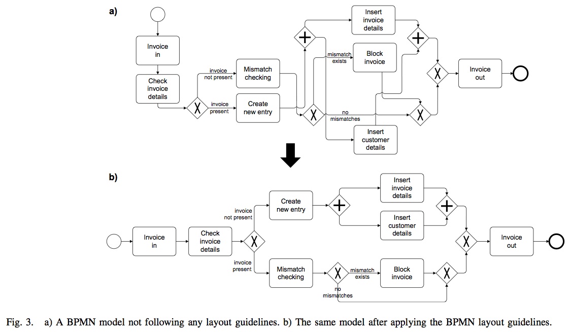
Figure 3: a) A BPMN model not following any layout guidelines. b) The same model after applying the BPMN layout guidelines.